West Clare Railway Railcar 4mm Scale |
|
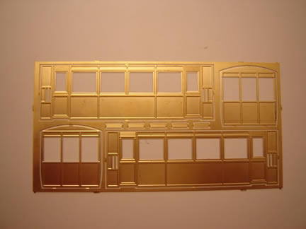
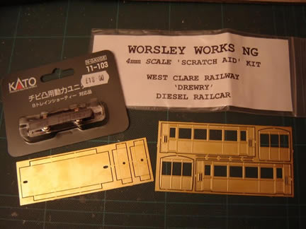
A RAILCAR PROJECT West Clare Railcar Built by Michael Campbell and copied with his permision from his Blog started in January 2010 "..............I've finally got around to starting a railcar kit that I picked up at Expo NG in October. Well, I say kit, but it is a Worsley Works "Scratch Aid" kit, and consists simply of the sides, ends, and a floor for the railcar, etched in brass. I also got a Kato 4-wheel chassis that should fit nicely, albeit with somewhat small wheels, but I doubt that will be obvious when complete. So there will be quite a lot of extra work involved with this one, mating the body to the chassis (it isn't designed for any particular chassis), adding glazing, interior, a roof, underframe, and all the other details needed to complete the model. |
 |
|
|
The prototype for this railcar was one Drewry supplied to the West Clare railway in Ireland in 1927, it was actually made by Baguley. Of course it was also 3' gauge, but it was quite small so will look fine against my stock, which is mostly based on 2' to 2'6" prototypes. The specs were: - weight: 5½Tons Thanks to help from the NGRM forum, I also found some prototype photos, which seem quite hard to come by, at the Clare Library website, Here and Here. The Weston, Clevendon, and Portishead standard gauge light railway had a similar design of railcar from the same company, as seen here. Now I've fancied a railcar for Awngate for a while, but many seemed to be too modern, required turning or running in pairs, or just looked a bit tricky to model! This one seems to have the right character, size, and being a generic sort of design from a company that sold to anyone (rather than a design associated with a certain line), it should seem at home on Awngate. I've already made a start on assembling the body, so more updates should follow soon. |
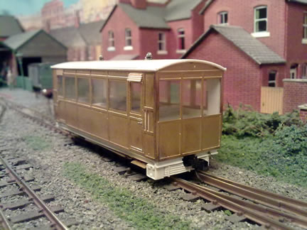
| BOLD AS BRASS Now I've not worked with etched brass much before, other than a simple diesel kit (where I used epoxy glue) and the cab of the Ruston I built a few years ago. So this is a bit of a first, and I did consider glueing the body together around a plasticard inner body. But that would be cheating, and more to the point, I knew it would be much stronger if soldered. I'm used to soldering wires when wiring up the layout, but I don't have flux, special solders, shaped iron bits, etc., however in this case I have managed (just about) with conventional multi-core solder and a standard Antex 25W iron. Reading Phil Parker's guide in this months Hornby magazine, other than the lack of flux I was not far wrong! Still, it seems to have worked ...
|
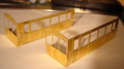 |
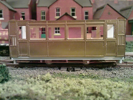
Eventually I got the whole body assembled, pretty square and without
much solder on the outside. The corner joints have come out pretty well,
so I'm pleased with the result! |
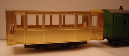
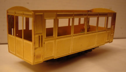
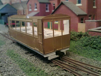
Here it is on the chassis, posed next to a Vale of Rheidol brake van
(by Parkside Dundas) to give an idea of size. I mounted the brackets
for the floor 3mm up the ends, so the chassis is set about 2.5mm up
inside the body, which looks about right - possibly slightly lower than
the prototype but will look in keeping with my other stock. |
|
|
Don't forget this kit isn't designed for any particular chassis, so I have had to cut a hole in the floor to accommodate the Kato chassis. That was hard work, I don't find brass as nice to work with as plasticard. The floor is intended to bolt up into the body using the holes in the brackets at the ends, as shown below, thus allowing the chassis to be attached to the floor and glazing to be fitted after painting. However here I am not sure. The body will be much stronger if I solder the floor in place, using the side tabs to reinforce the body sides. It will be easier to add glazing and an interior from above, as will be painting it without a roof, so I will have to make the roof (not supplied) removable anyway. In any case, those bolt holes will clash with where I would want to mount couplings, and I will need to add underframe detail below the floor too. So that leaves me with the problem of how to mount the chassis - I can't get it to clip in, I might be able to drill holes through the coupling pockets for bolts, but that means new holes in the floor ... |
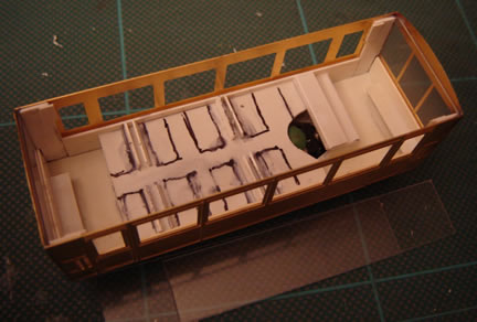
RAILCAR INTERIOR The railcar has been making steady progress recently, an hour or two at a time in an evening, although it doesn't look like dramatic progress! Layers of 40-thou plasticard have been added above and below the floor, cut to be a tight fit around the chassis, such that it seems to stay in place with friction at the moment! However the main focus recently has been on the glazing and the interior, which because of the large windows all round, will be very visible. In the corners of the body, between the doors and the end, plasticard was built up to make the recesses behind the handrails. Strips of 20-thou plasticard were cut for the panelling up to the windows, and these were glued in place with packing strips so that they form a slot for the glazing - cut from 20-thou plasticard - to slot into. The end glazing also slots behind the plasticard corner pieces. The pictures hopefully show this better than I can describe. |
 |
|
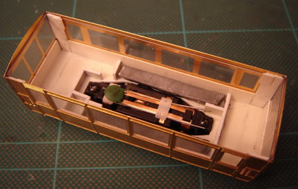
I've been given a drawing of the interior, which has been most helpful. I thought the best way to hide the chassis was with a dummy floor, made from 40-thou plasticard. This left enough space either side of the chassis for a couple of strips of roofing lead - in this scale the more weight the better, and it does help make the running more smooth. With the dummy floor in place (the cut-out is to clear the capacitor, which is the highest part of the chassis) the tops of the seats have been glued on, and the end seats made up. The wide strip at the right-hand end would be the engine cover. The floor is about 3mm higher than it should be to rebate the chassis to the right ride-height., and the dummy floor over the chassis is only just below the window line, so any passengers will have to suffer major surgery in order to fit! |
RAILCAR - TACKLING THE UNDERSIDE! Recent progress with the railcar has focussed on the underframe and all detail below the body. This has highlighted that as a "scratch aid" kit there is an awful lot of scratchbuilding involved! First two layers of 40 thou plastic plus further packing has been added below the floor, which had been set further up the body to get the chassis the right height. The plastic extends slightly below the lower beading as per the photo's I have. Then an underframe was added from plastruct "H" section - allowing for couplings. The very distinctive radiators under the ends were made from plasticard scored with a razor saw, giving the grille effect, then detailed with microstrip strapping, though they have been cut around the coupling. |
 |
|
The Kato chassis has had as much of the "N-gauge" detail removed as possible, but the plastic frames hold the wheels and motor in place so care was taken not to weaken them. Very simple detail was then added for W-irons, axleboxes, and truss-rods, from plastic. Not much of this will be visible! Incedentally the chassis is now a fairly tight fit into the plastic hole left under the body! Much thought was given to the steps - although the prototype has two steps to each door, I settled on one, as this model has been built lower and on smaller wheels than the prototype. I was also concerned that lower steps might hit platforms, as well as being very vulnerable! The steps were made from off-cuts of the brass etch and soldered to springy wire, which was then bent to suitable supports and glued into holes in the floor behind the solebars. Hopefully this would make them robust enough! |
|
Finally the prototype railcar has some unusual and distinctive rodding (or pipework?) along the side of the chassis, I think these are controls to the driving positions but I'm not sure. Since they are always in shadow, and hard to see clearly on prototype photos, I have made a representation from micro-rod. |
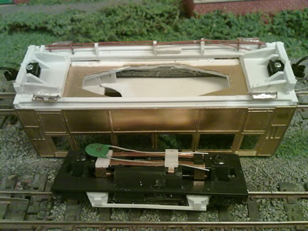
This view of the underside of the body, and the chassis removed, shows the basic detail on the chassis as well as the plasticard packing under the body, supports for radiators and details, the brass and wire steps, and how the Microtrains couplers are screwed into place - they can be removed for painting. |
|
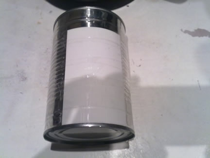
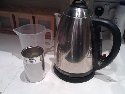
THE RAILCAR - A KETTLE AND SOME PLASTIC... OK progress has been interrupted a bit lately, but I have completed the roof! The kit didn't come with a roof - and I'm not sure I could have rolled a brass roof to the right shape anyway, so again I have reverted to my usual plasticard. The trouble with plastic is that it doesn't stay bent - unless that is you give it a hot bath! So two pieces of 20-thou plastic were cut to the lenght of the roof but over width, and taped to a used tin can. Then I put the kettle on ... ... no not more tea! Here's how it is done. Put said tin into jug and pour in boiling water. Allow to stand for a while (now have your tea!). Empty away, rinse in cold water, and then remove the tape. Hey presto, curved plasticard! Simple but effective, and not my idea - I've done it before but can't remember where I first hear about it. This tin was pretty close to the right radius, slightly too tight, which is fine as it is forced to the right radius later. |
I said two pieces of plastic were bent - one was trimmed to the roof size with slight overlap over the bodysides, the other cut to fit just into the bodyside, then the two were cemented together - there is no way that bend is coming out! To make it even stronger I cut a piece of 40-thou plastic to fit inside the body like a ceiling, and - here's the fiddly bit - 4 small pieces to the curve of the roof to act as "ribs" like this: ( - which were glued to the false ceiling, then the curved roof stuck over the top. It is now really solid, and exactly the right radius! It is a faily tight fit into the body and helps hold the sides rigid, especially when being picked up, when painted a spot of PVA will hold it in place such that it could be prised off if needed. |
 |
 ` ` |
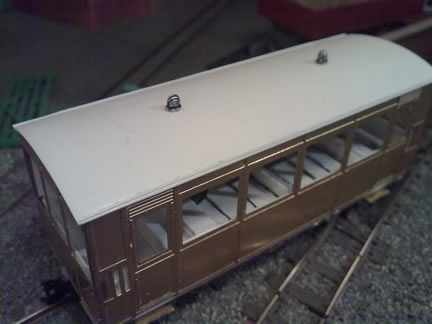 |
Finally I found some lamp ventilators in my bits box - whitemetal castings of unknown origin - and added a couple as per the photo's I have. Also some fine microstrip makes the rainstrip along the edge of the roof. |
|
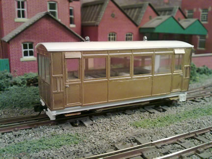
| RAILCAR READY FOR PAINTING I've just completed the final details, so the railcar is now ready for painting. Well, it needs a good clean and polish first, but there's not much point in doing that until I am ready to paint it! The trouble is, I don't have any etch primer and I'm not sure my usual Halfords primer will be the best for brass, so painting might be a little delayed.
Final details included door handles (bent s taples), the ventilators over the doors (from the etch), a battery box and more unkown rodding under the side shown, and a starting handle on the "front" (right of coupling in the lower photo). The glazing cut previously was trimmed to clear door-handles and roof and slid back in (of course it will be removed for painting). I did wonder about putting driving controls inside, but since they are not visible in photo's and I am not sure where they would be, I thought better not to guess and get it wrong. However I will also need to amputate the legs of some passengers! |
 |
|
So final verdict on the kit? Well I am still not a
fan of brass, plastic kits are much easier and to my mind, the results
just as good. Also the description of a "scratch aid" kit is
spot-on, although the sides are nicely etched and you don't have to cut
the windows out, the rest of the model has to be scratch built, and to
build anything approaching the prototype research is required too. I have
found a lot of help on the NGRM forum as well as through comments on this
blog, a real benefit of the internet! But for models of less-well known
prototypes the Worsley Works range are a big bonus.
|
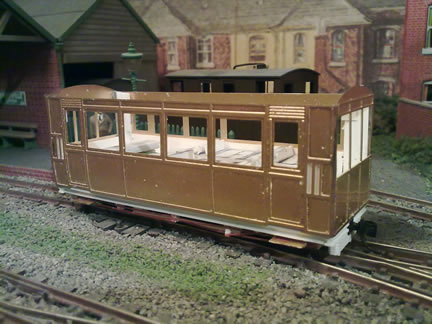
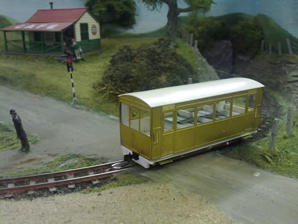
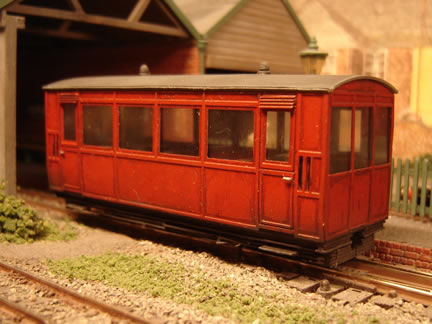
| The Railcar has been with my friend Rob Kaczmarczyk for painting, and
today I got it back. And he has done a great job!
Despite the fact that all my other passenger stock is green, this railcar seemed to suit red best - although I have no idea why! And so red it is. I also wanted a "wiped-clean" look, not uncared for, but a well-used look. Rob's subtle touches with the airbrush have really brought out the panelling and underframe detail. All it needs now is the couplings re-fitting (in case of a luggage trailer being required), and of course some passengers!
Michael has made a fantastic job of building the kit and we thank him for allowing us to reproduce this part of his blog on our web site |
 |