
 |
|
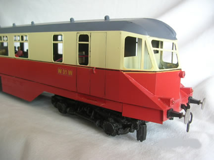
AEC Diesel Railcar Construction Notes for 7mm GWR (Razor) Diesel railcar No's 19 - 32 by Kerry Vinney |
|
 |
 |
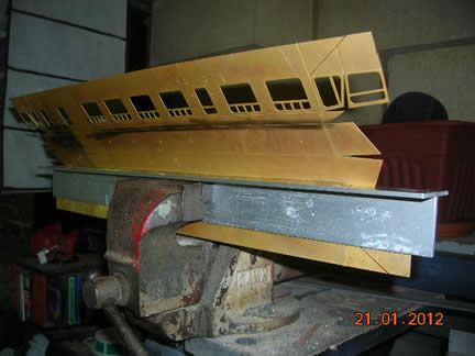
Having removed the one piece body etch from the fret with a Stanley knife or Dremel disc cutter, clean the tags off and carefully study the assembly pictures. I used a pair of 3mm angled aluminium pieces at least 500 mm in length. The extra length is required so that heavy duty screw clamps can clamp the outer edges and enable a straight bend to be achieved over the whole length. Starting at the roof centerline clamp the etch in a firm vice and when the etch line is parallel with the aluminium bar, bend it slightly using a piece of dressed timber or aluminium so that it folds evenly over its whole length. |
|
 |
 |
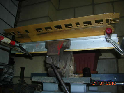
| Next, first one roof side then the other in the same manner,
then the cab sides themselves. Using the solid partitions bend the body into the final shape. |
|
 |
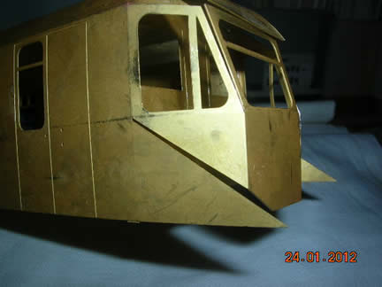 |
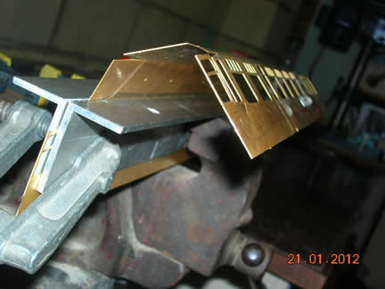
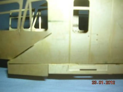
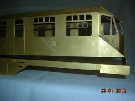
| When satisfied that the body shape is correct and symmetrical with the eye in various directions, tack solder the driver partitions in place in the half etch grove, making sure that they are pressed firmly onto the roof section and at the same time help to form the roof shape. Bend the roof fronts down in a sharp curve first then driver cab section into shape and when lined up satisfactorily tack solder together on the inside. |
|
 |
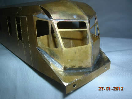 |
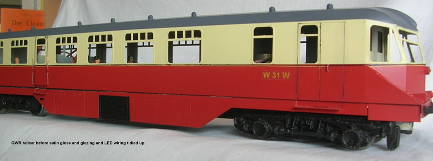
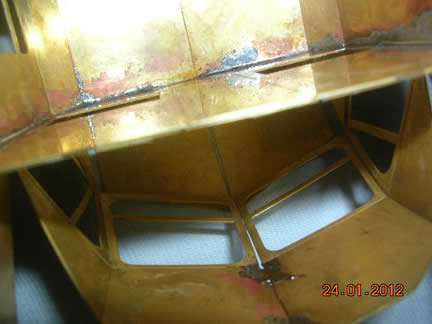
| The two roof corner gaps are filled in with epoxy putty and sanded down later. Now make a final check with the eye that the body is uniform in shape and that it sits evenly on a flat surface. Now spot tack solder over the joints and then finally joining them together. Bend up the underframe etch and solder in the steps. U sections will
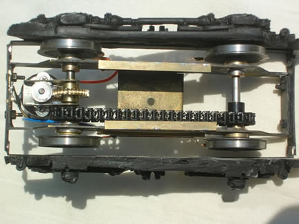
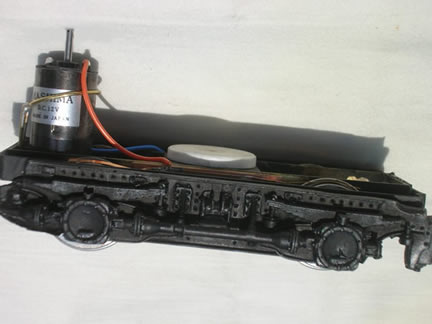
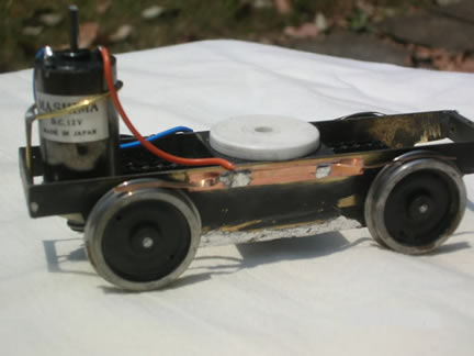
need to be cut to give clearance for the buffer shanks. The bogies are scratchbuilt as shown in the photos below |
|
 |
 |
 |
GWR razor railcar bogies . Items list: |
| With reference to the photos of both the power bogie and the trailing bogie, cut 4 X 120mm pieces from the 12mm strip. Secure together by temporary soldering the ends together. Cut outline shape of bogie frame using template from 7mm drawing. Mark and drill bearing holes at 8’ 6” (59mm) centers, and then desolder and clean up. Now using the 6.0mm strip, cut 4 x 22mm and 4 x 37mm pieces. Clamp one 22mm piece to a 37mm piece equally spaced from each end and drill a 10BA ( or 8BA ) clearance hole 15mm apart, and bolt together. Using a piece of glass assemble up the inside frames with their bushes and fit the wheels and axles with a small spacer washer between the bearing and wheel and then solder the bolted units one each end with the shorter piece inside the frame. Solder the bushes. This should give a free wheeling unit on the glass. Repeat the assembly for the unpowered bogie. Cut the protruding axle ends off. Cut 4 x 122mm pieces, mark 5mm in from each end, lightly grind or file a grove and bend 90 degrees at the grove. Solder these to the end pieces so that they clear the wheels. These side pieces hold the cosmetic bogie and when the 4 bolts are removed the outside rectangle will lift away from the inside unit to allow the wheels to be removed and the motor and gearbox and sprockets and chain to be fitted. I superglued a PCB strip to the side and soldered a phosphor bronze strip bent to curve over the wheels for the power pickup. |
|
|
|
 |
|
| Reference Material
Great Western Diesel Railcars J H Russell ISBN 0 906867 30 4 |
|